SAWDIS - KITE WEATHER RESEARCH PROJECT
Well time has now arrived to re-start the KITE PROJECT but under a new umbrella. This project will be launched in several fases and I will update these pages as the project unfolds.
SAWDIS - KITE CARRYING WEATHER RESEARCH INSTRUMENTS PROJECT, is a Southern Cape based project that promotes science and education by exploring different kinds of frontiers with medium to high altitude kites. Several individuals will assist me and their names and contribution towards the project will be displayed under this topic. We are simply a few individuals with similar interests and a common goal to experiment, which anyone is welcome to participate in. Our aim is to help promote education, experimentation amongst interested people in South Africa.
BACKGROUND:
I always had this crazy idea of in sending “something” up in the sky with a payload on board. I had a look at several helium balloon and rocket projects but due to various Governmental and Aviation “red tape” in this country, I decided the next best option for the time being would be to use a kite to carry the payload. You might say what a waste of time but did you know that a World Kite Altitude Record of 14,509Ft (4422 meters) was set by Richard Synergy in Kincardine, Ontario, August 12, 2000 for a single kite. Needless to say I am not currently interest to better the record. The aim of this project is to build a kite that will carry a weather and science payload.
START OF THE PROJECT:
A diary of events and an inventory list of scheduled activities will also be kept to ensure that every aspect receive the necessary attention. I will not go into all the detail of the project as time and space does not allow it.
MAIN ACTIVITIES RELATING TO THE PROJECT:
1. KITE(S)
2. PAYLOAD(S)
3. FLIGHTS
4. RESULTS
5. RESEARCH
6. FINDINGS
7. FUTURE
KITE(S) FOR THE PROJECT:
Research on the Internet revealed many information on kites. I had the option to buy a ready-made kite or to build a kite for the project. It had to conform to certain specifications.
I decided on the DELTA KITE and to built it from scratch. The delta is a light wind kite, particularly suited to thermal cruising. It is relatively easy to construct and conveniently quick to assemble. Delta kites are single line triangle shaped kites that are sometimes called "bat" or "wing" kites, and are named for their resemblance of the Greek letter "Delta". A very efficient kite, the delta kite can float in lighter winds than most other kite shapes. The exceptional lift capabilities of the kite allow several kilograms of payload to be attached to the kite and/or tether. Just what we are looking for.
I am also looking at several variants of the Delta Kite for the project. The first experimental kite will however be a delta with the following specifications. (Please note that this kite is small and is only for test purposes.) If this kite "performs” satisfactory, a larger (6 meter) version will be constructed for the project.
Well thanks to the family the K.C.A.R prototype kite was build and is now ready for it's maiden flight. The decal is still to be affixed and a trimming here and there will see it ready for final testing.
Photo of DELTA I in flight:
Images: Johan van Aarde ( SAWDIS Weather Observer) Click on images for larger view.
PROVISIONAL PAYLOAD FOR THE PROJECT:
The current suggestion is to accommodate the following equipment as a payload:
1. UHF TRACKING BEACON (INTERNAL AND EXTERNAL)
2. APRS TRACKING UNIT
3. TEMPERATURE SENSOR UNIT
4. FIXED DIGITAL OR DISPOSABLE CAMERA
5. BAROMETRIC, TEMPERATURE AND HUMIDITY CENSOR UNIT
6. WINDSPEED CENSOR UNIT
Some more info on these units:
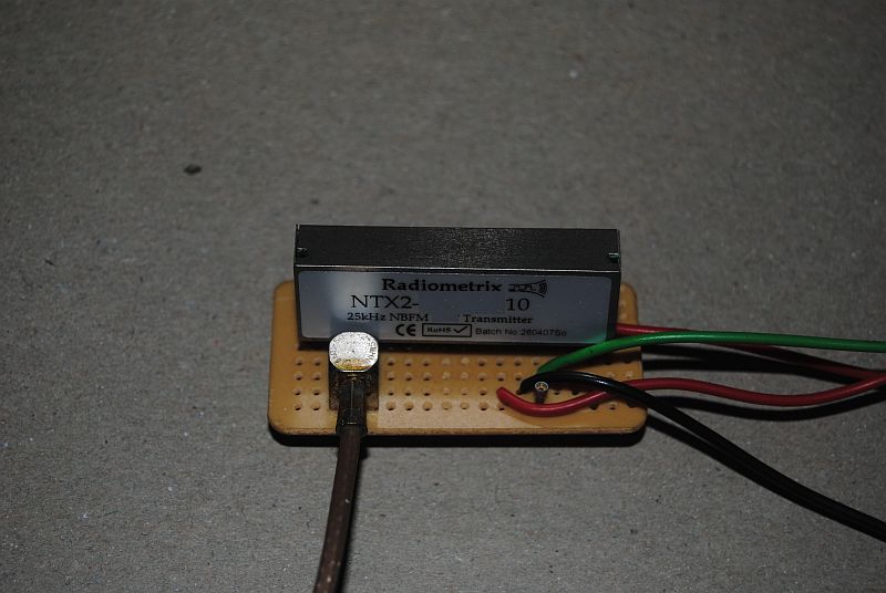
UHF TRACKING BEACON: I intend using an AM UHF Transmitter (10mW)with temperature sensor unit. Not only will this provide for an internal beacon but I can also connect a beeper to the unit for external audio. The transmitter will also be used to transmit temperature data to a laptop computer.
APRS TRACKING UNIT: I intend using the TinyTrak 4 unit. The TinyTrak4 (TT4) is a radio interface capable of transmitting and receiving position and other digital information over a two-way FM radio. The TinyTrak4 can read temperature, battery voltage, and other analog and digital sources which makes it ideal for this project.
TEMPERATURE SENSOR UNIT: This unit will work with the TinyTrak 4 unit and will transmit temperature readings via the beacon.
FIXED DIGITAL OR DISPOSABLE CAMERA: I will most probably use a disposable camera to start with. (Cannot afford to crash a digital camera at this stage) It is envisage to take pictures of the surroundings and activities on the ground. Will have to use a servo with some kind of transmitter to activate the camera.
BAROMETRIC SENSOR UNIT: I will use a Oregon Scientific Wireless Baro-Thermo-Hygro sensor unit to display barometric pressure, temperature and humidity information. This info will displayed on a Oregon Scientific Weather Station at the "airfield".
WINDSPEED SENSOR UNIT: Windspeed will be recorded by a Speedtech Instruments unit. This unit can display a variety of data in different settings.
Further updates to follow.
Constructing a DELTA-CONYNE KITE
With the weather being fowl this last couple of days, it was ideal to start work on this post on how to build a DELTA-CONYNE KITE. I received several requests to make the plan availble as many would like to build this kite for their grand children. I drew the plans for this kite on the 16 June 2008. Here are the dimensions of the kite.
(Click on image for large view.)
The kite is 2.8 meters (9 Ft) from tip to tip. All measurements in centimeters. For those interested here is a short overview of the kite:
The Delta Conyne is a kite which gained popularity in the late Seventies and early Eighties. It is a hybrid kite, being a combination of a Conyne, which is a box kite, and a Delta. The kite is very stable and will fly well in a large variety of winds. The lifting power of a Delta combined with the stability of a box kite, these kites are always the fastest climbers in altitude races. This kite is capable of lifting large payloads and is truly impressive in the sky.
In a moderate to stiff wind it flies well and will lift a reasonable payload. To give you a rough idea say the payload weighs in at roughly 820 grams. I can fly the Delta Conyne in any wind from about 10 km per hour but to lift the payload its nearer to 15 km per hour to be safe. Years ago I invested in a portable anemometer which will now come in very handy. Now building this kite was real fun and guess what I had to sew the kite myself. The YL point blank refused and I had to get behind the sewing machine. Learned something new and can now operate a sewing machine.........yep and this does not make me a lesser man. At least I can now mend my own clothes!!
This project has really focused my attention on flying kites as a past time. I have learned a lot about flying kites and also the many uses for kites. Now you may ask why fly a kite? Each flight is a journey of exploration. Each flight is different. And the flyer is not merely a passive observer, either. The responsible flyer is in control at all times (or should be): letting out line; not letting out line; winding line in - to catch lift, turn, take out more line, move to another spot in search of a thermal - all done deliberately by the flyer in control. Kites are controlled by pulling in or letting out the line. With the right kite for the wind, and the right line, it's very relaxing and rewarding. Flying a kite for an equal number of hours showed a cost effective means of reducing stress. It was also the best in terms of overall effectiveness, regardless of cost. A further bonus is to combine kite flying with Amateur Radio. Marconi lead the pioneering actions as far back as 1901 - Guglielmo Marconi used a kite to lift an aerial to make his historical radio link between North America and Europe.
Enough of history, I must now sit and wait for the weather to be conducive for kite flying. The next step will be to manufacture a Picavet. The Picavet will provide a level platform for the science payload.
The maiden flight was a great success and I am impressed by the handling and lifting capability of this kite. My thanks go to Johan van Aarde for the photo's and I am sure you will agree that they are of outstanding quality. Here are some of the photos that were taken of the Delta Conyne 1 in flight.
Images: Johan van Aarde (Click on images for larger view.)
Constructing the PICAVET.
I received several e-mails from blog readers wanting to know what a PICAVET is. The Picavet is named after a French inventor in the early 20 th century. I will attach the payload to the kite line and not the kite. The angle of the line to the kite is constantly changing. To provide a level platform for the payload I will use the Picavet. The payload hangs beneath the Picavet cross from a bolt that is fastened through a hole at the center of the cross. The Picavet has an inherent dampening effect as part of its design. As the kite line changes angles a Picavet moves to the new level position and stops. The lines of the Picavet also provide dampening of wind induced vibrations on the kite line. The diagrams below show the major parts of the Picavet.
I constructed a 150mm x 40mm x 1.6mm Picavet Cross and used 5 eyebolts, 1.5mm line, small washer and two keyholder rings. To prevent the eyebolts from loosening in the wind I used lock nuts on both sides of the cross.


I contacted Johan ZS2I and we decided to go ahead with the testflight. Myself , Johan ZS2I and Sewes set out to the "airfield". We first decided to let the kite fly without the picavet. I took the kite to approx. 100 meters. It flew beautifully and just "sit" up there. Very little movement. The wind at that stage was blowing between 10 and 18 km/h. The next test was to attach the picavet. The picavet was tied to the kite line about 4 meters from the kite and two fishing sinkers were attached to the picavet. Needless to say that the distance from the kite to the picavet was to short. The "payload" swinged fiercely from side to side. We hauled the kite in and added another sinker and lengthened the distance between the kite and picavet to about 10 meters. The wind took the kite and it just went up and up. Johan ZS2I : "Die kite wil net op en op, gee hom lyn, laat hom gaan. All in the name of science! "
It went up to about 35 meters but then disaster struck, the wind was not strong enough to carry the payload (348g) and line any higher. Not deterred by the light wind, we decided to do another experiment. We removed the sinkers and attach a portable anemometer and temperature sensor to the picavet. The kite went up again to about 40 meters. The anemometer was adjusted to give us the maximum strength of the wind and temperature. After about 15 minutes the kite was lowered and the measurement showed the maximum wind speed as 31,3 km/h and temperature as 17.7 Degrees Celsius. These measurements were taken 35 meters above the ground. The kite was again send up to about 35 meters with the sinker payload. Then disaster struck a second time. With the approaching cold front the wind suddenly picked up in strength. It got so strong that it was impossible to hold onto and I decided to give it line to release the pressure. The wind increased in strength and the kite shot up to approx 300 meters. It entered the "Stratosphere". You don't believe me. Looking at the photo (taken from a light aircraft), you can just see the earth at the bottom of the photo.

Photo: Kite flying above the clouds in the "Stratosphere". Earth visible at the bottom of the picture.
Yep, we then hit the Statosphere. The wind suddenly decreased and the kite glided through the clouds back to the "airfield". (Note: Just kidding about the Stratosphere and flight above clouds but a light aircraft did explore the strange object in the sky. Luckily it is red and white obviously noticeable from quite high up. We flew for another 15 minutes and called it a day after the wind decreased even further.
What did we learn:
1. The wind speed to carry a 557g payload must be between 35 and 45 km/h.
2. The size of the kite in light wind (10- 18 km/h) should be at least 5 meters from tip to tip.
3. The 2.5 mm kite line that is currently used, is to thick and to heavy for the 2.8 meter Delta Conyne.
4. There is a need for at least three different sizes of kites to fly in different wind strengths.
5. Leave enough line length between the kite and the picavet to ensure a steady flight.
Although this flight might sound dull and useless, we learn from experience, something we definitely will need when the time comes to fly the real payload.
We once again had great fun. Many thanks once again to Johan van Aarde ZS2I who took photo's during the flight.
Testing the PICAVET in stronger wind.
Testing the PICAVET in stronger wind.
Well this time the SA Weather Service got it right. A 42.8 km North Westerly in Mossel Bay at last. Myself and Sewes just returned from the "airfield" where we tested the 2.8m Delta-Conyne. Oh.......what an experience!!! Sewes was the anchor man and I did the flying. No time for errors here and you had to hold on for dear life. The wind just took the kite and within a couple of seconds it was soaring around 50 meters. I soon realized that I needed all the experience I have to keep it from going up and up. I slowly started to haul it in. The leather gloves bear the scars of the strong wind. Just imagine if you had to fly the kite with your bear hands....totally impossible....you would have no fingers left. When we had it about 20 meters up I decided to add the Picavet with 5 sinkers and anemometer (550g). Guess what when I released the rope it just ripped the sinkers up into the air like a balloon. The kite would easily have lifted 800 grams. The wind was getting stronger and we decided play it safe and to bring the kite down. Once down I decided to take of the payload and let the kite go one more time. It shot up in the air danced once or twice and than a loud bang. The kite folded it's wings like a duck that was shot and started to come down like a wounded duck. It landed and we decided to call it a day. Once we got to the kite I noticed that the main spar had snapped in the strong wind and that's what caused the kite to fold it's wings. The anemometer measured 42.8km. We packed up and headed home.
Some thoughts:
1. Ensure that your equipment can withstand the wind you fly in.
2. If you use ordinary wooden dowels than a 30 km wind is to strong.
3. Do not fly the kite in strong winds if you are inexperienced.
4. Ensure that you can control the kite in this type of wind.
5. Use fiber glass- or carbon fiber spars.
6. Never fly a kite alone.
7. There is no time for errors.
8. Take care not being caught in the kite line.
9. Wear the proper protection gear.
10. Do not fly a kite near houses or overhead power lines.
We had a great time flying the Delta-Conyne in the strong wind. I would however suggest that you do not fly this kite in more than 45km winds. However we gained some good flying experience and will make changes to the kite spars and to the kite itself.
Aquilone 1 Payload Construction
The SAWDIS Kite Project is well under way. I am currently busy with the payload construction and hope to make the first payload test by the end of this week. Here is a few images of the different electronic projects that will be installed in the payload bay.
GPS Antenna installed on PCB
GPS UBlox unit which will be connected to the Modified TinyTrak1 board for APRS tracking
Modified TinyTrak1 PCB which forms part of the APRS Tracker Unit
Meteo Board with Barometer, Hygrometer, Temperature meter and transmitter to transmit weather info to computer.
Transmitter for APRS Tracker unit. The transmitter will transmit the exact location of the kite.
RS232 converter for converting GPS data.
The payload tray showing two compartments. There will be 6 compartments in the final tray assembly.
The payload tray (Side view.)
The payload housing with two end caps.
The payload bay with two end caps (Side view.)
The payload bay and tray.
The payload bay and tray. (Side view.)
(Click on images for larger view.)
Assembly of the Aqualone 1 payload
Great news. I finished the assembly of the kite payload. The "smoke test" on the SAWDIS Auqualone 1 Kite Payload was performed yesterday afternoon. The result: No smoke! The payload performs well and final testing will be done later today.
I still need to build antennas for both the APRS Tracker and the WX Transmitter. Photos of the payload will soon be published. I am looking forward to the first flight of the SAWDIS Auqualone 1 Kite Payload. All the transmitted data of the SAWDIS Auqualone 1 Kite Payload will be available on the Internet in real time format. More information on this in future updates.
The Aquilone 1 Payload
The SAWDIS Scientific Kite Payload
The payload is now fully constructed and operational as can be seen from the images. The first flight of the Aquilone will soon be taking place and I will announce the date and time in due coarse. I still need to compile a few flight maps for the APRS unit to reflect the exact position of the kite. The weather data will be fed into a local weather station and then displayed on the Weather Underground web-site. Once all the software programs have been installed and updated we will be ready for the first test flight.
The payload cover with insignia and SAWDIS payload
The GPS Antenna and GPS Unit
The RS232 Converter and TinyTrak 1 Controller
The Baro - Thermo - Hygro unit
The Transmitter, Battery and Power Controller Units
The Power Controller Display
The APRS Antenna attached to the payload
The SAWDIS Kite Payload exposed
Image: SAWDIS (Click on images for larger view.)
- ZS1I