As the title indicates, certain activities changed in Amateur Radio due to Covid19. Whether some changes will be permanent in future need to be seen. It is currently to early to come to any conclusions or final decisions. However we must adapt to circumstances or be willing to sacrifice certain pleasures in Amateur Radio due to the Covid19 virus.
One such activity is monthly public get togethers or club meetings. In our area we have a club as well as a group of radio amateurs that get together. The club has quarterly meetings while the Reboot Group get together on a monthly basis. Since the pandemic outbreak started all meetings were stopped/postponed. As the pandemic progress it is clear that it will take some time before we can hopefully safely get together again.
I suggested we use ZOOM at this time as to stay virtually in touch with each other even drinking a cup of coffee while in a ZOOM meeting. What we have done before can now be done safely with ZOOM without the risk of getting infected.
Setting up a "studio" to broadcast meetings etc. is now underway and we will do the first test streaming on the 1 July 2020 at 19h30. To make sure that the video quality will be acceptable I needed to install/gather equipment. The three main "ingredients" for a good video broadcast is: 1. Good Audio 2. Good Lighting and 3. Good Video. Many of the equipment needed are currently not available due to the fact that the public bought most stock to stream various services etc.
I needed to think out of the box to get a simple yet acceptable small "studio" up and running with equipment on hand or easily available. For audio I decided to invest in a USB microphone. I do have an "elaborate" mixer, sound interface and dynamic microphones on hand but decided to buy the FiFine K669B microphone for ease of use and the availability of space. This microphone is also used for WhatsApp, Skype, Zoom, Echolink and AllStar and has shown to be a relative good cheap performer.
Setting up the microphone is a breeze and the final results are amazing for such an inexpensive microphone.
Good lighting was next on the list. Now my space for a "studio" is very small and I needed to make sure that I do not clutter my work area even further with lights, mics, stands, cameras etc. For lighting I chose a cheap Chinese LED light which already has a diffuser installed. This light was manufactured to install into a ceiling and not on a tripod or overhead stand. I modified the light and it can now be used in many formats. I made a bracket that screws onto the back of the light. This allows for easy fitting to any object or stand. It is not the brightest of lights but will be used as a fill light. I intend to use a three point light setup to start with.
Now this project is far from complete. This topic will be updated as I progress with the project. I am currently looking at building an overhead or wall mount stand which will hopefully also save on the amount of space. To mount lights, cameras, and other accessories I need a sturdy overhead rig. I have not yet decided on how I will build mine but have a few ideas up my sleeve.
I am busy constructing a swing arm that will be used to mount either a microphone or a camera. It is sturdy enough for a microphone or a camera. I still need to make the mount to attach to either a wall or overhead rig. The images underneath depict the swing arm.
My green screen that I will be using on ZOOM and OBS under construction:
Busy constructing my H-Frame Light Stands:
Updates to follow as I continue with the project. Please check back from time to time if you interested in Virtual Amateur Radio Meetings.
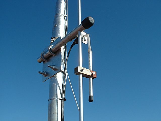
Kevern ZS1ABU writes: I will post a few pictures of a Yagi we build a few years ago. It was build mainly to use for the Pears and SARL VHF/UHF Contests. We received many 1st and 2nd places using this antenna. Its cheap to build and all the hardware can be bought from Builders Warehouse, except the little standoffs which was made by Dieter ZS1DWH on his 3D printer. This was made from plans and examples on the well known website : https://www.qsl.net/dk7zb/Duoband/4+5_2m-70cm.htm
DK7ZB writes: The 4-El.-Ultralight-Yagi
for 2m can be used on 70cm with an SWR of 1,5 without any
changes. The pattern and the currents of the Yagi are shown down. The Yagi has
three forward lobes (according to the three current maxima in the
3/2-lambda-radiator) with 5,39dBd - 4,35dBd -5,39dBd gain. We can use this Yagi
without any changes on 2m and 70cm.
Click the link HERE to watch the video of the Crystal Radio in operation.
Danie ZS1DBJ George: Môre Johan. Hoe ver is jy van die AM sender?
Abe ZS1ZS Mosselbaai: More Julle, Ons het 'n spoel gedraai om toilet rolle
Abe ZS1ZS Mosselbaai: en minora skeer lemmetjies gebruik vir verstellings kapasitors en 'n ou kristal oorfoon gebruik om te luister. Was nogal lekker. Johan pragtig jou spoel en luispreker / versterker
Johan ZS6IW Denotter Hi. Seker so 40 km.
Die ander twee is kerkstasies wat nog altyd op MW is.
Danie ZS1DBJ George: Ek het weer bietjie gespeel met my magnetiese lus antenna en ingestel op 18.1Mhz. Coax gebruik vir die kapasitor. Elke cm is ongeveer 1pF.
Hentie ZS1LH Mosselbaai vra: Danie sal die lus kan resoneer op 3,67 en/of 7,100? Ek dink aan iets vir Danabaai as ek daar tussen die klomp ou mense gaan woon.
Nick ZS1N Boggomsbaai vra: Danie wat is die omtrek van die lus?
Danie ZS1DBJ: Nick hier is mates. Verkoeling tipe koperpyp.
Abe ZS1ZS Mosselbaai: Danie is ons boffen met Magnetiese Lus Antennas. 80m mag dalk 'n opsie wees Hentie, darem nie te groot nie.
Abe ZS1ZS Mosselbaai: Wag so 'n jaar gelede by Henry ZS1AAZ en hy het 'n monster gemaak wat 'n vacuum tube gerbruik. Hy het ook 'n MFJ wat hy in sy agterplaas opgesit het. Ook 'n probleem met kompleks wat nie van antennas hou nie.
Danie ZS1ZS George: Nie boffin nie. Maar wel proeffin. Net proefnemings. Vir 80 meter moet die lus baie groter wees.
Magnetiese lus antenna deur Danie ZS1DBJ. Die koperlus het ń diameter van so 650mm en is gemaak van 16mm diameter koperpyp. Die koperpyp is afkomstig van ń verkoelings besigheid. Dit is sagte koper en maklik buigbaar. Die plastiese houers is afkomstig van gordyn reelings. Die kapasitor vir die lus bestaan uit RG213 coax. Die kapasitansie vir die coax kapasitor was bepaal deur ń verstelbare kapasitor op die lus te koppel en met analiseerder die waarde te bepaal vir resonansie teen 18.104Mhx. ń Lengte RG213 coax is toe aan my kapasitansie meter gekoppel en stukkie vir stukkie korter gemaak totdat coax kapasitor en toets kapasitor se kapasitansie lesings eners was. Die gesnyde coax is toe aan lus gekoppel en met behulp van antenna analiseerder verder "getrim" vir resonansie op 18.104Mhz. Die volgende stap is om 2 klein stukkies PC bord aan onderkant van coax aan te bring vir "fine tune" aangesien die antenna ń baie hoë Q waarde het en is baie gevoelig op verskillende posisies. Ek sal moet kyk na motor beheer vir die "fine tune" kapasitor. Lus se koppeling met radio is via die "gamma matching rod". Die verstelling vir 50 Ohm word gedoen deur ń kortsluit brug op die lus en "matching rod" te skuif. ń SWR waarde van 1.3 en Ohmwaarde van 50 kon bereik word. Die Icom 7300 se SWR toets fasiliteit het ook ń goeie SWR aangedui. Toetse is tot 20 Watt uitset beperk aangesien ek nie seker is van RG213 se isolasie spanning tussen geleier en afskerming nie. Op ontvangs is die antenna redelik vry van geraas.
During the December 2002 I worked up the design for this antenna purely by co-incidence. I needed two stainless steel self-tapping screws and my eye fell on the 3 element Yagi that I constructed for 2m operation. This “odd” measurement Yagi with stainless steel self-tapping screws were mounted on a mast 4m high from the ground. I unscrew and remove both the reflector and director elements in order to obtain the said screws. The driven element and funny looking boom were left intact on the mast. Later that evening I decided to contact Francois ZS1Q in George. I was greeted with the following remark ”Wat het jy nou aangevang? Jy blaas my uit die hok uit. Wat se versterker gebruik jy? “
I only then realized that I was using this “funny looking” Yagi. Tests were conducted and this led to the constructing of the odd measurement ”DIP-YAG” antenna. In amateur circles the “DIP-YAG” will rightfully be called a 2 Meter Dipole Antenna. Or will it? Be as it may this antenna give excellent results and is cheap and easy to construct.
To construct the antenna we first drill the hole for the element through the boom. Push the element through the hole and affix the element with a self tapping screw exactly in the center of the element. You will now have a T-shape antenna. Fit 2 X 10mm Plastic end caps to each opening of the element and 1 X 20mm plastic end cap to one end of the boom. The SO239 connector is affixed to a piece of aluminum plate bent in a “L” shape. A hole is drilled at the short end of the “L” through the plate, the SO239 is fastened with 4 X 8mm bolts and nuts. The long end of the plate is fastened to the boom with a rived-gun, approx. 80mm away from the element.
Photo: Showing the Gamma Match of the Dip-Yag Antenna
The gamma match consists of a 150mm length of 10mm aluminum tubing. The 200mm piece of RG213 co-axial center (the outer cover and braid is removed) is slipped inside this tubing which telescopes into the aluminum tubing. One end is then soldered to the connector. Sliding the RG213 center in and out of the tubing tunes the gamma match. Take the 60mm aluminum tube and drill two 10mm holes 25mm appart through this piece of tube. Fit the 2 x self-tapping screws on the side of this tube. These screws act as a “lock-nut” to tighten the element and the gamma match for the best SWR. Affix the boom with a mounting bracket to the mast. Note: The best SWR is obtained by moving this matching stub up and down, as well as the sliding of the RG213 center core in and out of the 150mm piece of tubing. After obtaining a 1: 1 SWR tighten all screws and affix the co-ax cable to the boom and mast with cable ties. One 10mm- and 20mm plastic end cap is affixed to the other end of the boom and to the end of the gamma match. Seal all holes and openings with an appropriate water tight sealer.
One of these “Dip-Yag” antennas works fine for a basic, slightly off center, omni-directional antenna. The angle of radiation is lower than that of a ground plane so it does tend to work better (I guess 3 db in the favored direction). You can use more than one by stacking them vertically. Losses might make it undesirable to stack more than 2 or 4. I am currently using a two stack arrangement with the following phasing harness measurements.
PHASING HARNESS:
2 X 1.36m 50 ohm RG58 co-ax cable
2 X 386mm 75 ohm Good TV co-ax cable
The 50 ohm and 75 ohm cable is joined together for each “Dip-Yag”. The 50 ohm length is affixed to the antenna while the 75 ohm section on the other side is affixed to a ”T” piece connector. A identical harness is made for the second antenna. A 50 ohm feed line is connected to the ”T” piece and fed to the 2m radio. Note the distance I used between the two antennas is 2 meters.
PARTS NEEDED:
3m x RG58U Coax Cable
1.2m x 75 Ohm TV Cable
6 x PL259 Connectors
1 x "T" Connector that except PL259 connectors.
15m x RG58, LMR400 or RG213 Coax Cable
IMPORTANT NOTE: Always use good quality connectors and cable to curb excessive losses. Bad connectors and cables will give bad results.
Seal all connectors and joints with a good quality sealer.
This antenna is quite broad-banded and performs well during static buildup in the summer months. Thanks to Nico ZS2N for the his MFJ Analizer and for the constructing of the phasing harness during his visit to Mossel Bay in April 2003.
I have done extensive tests with this antenna and has subsequently got rid of a Ground Plane Antenna, J-Pole and Slim-Jim. Construct this antenna and you will see why. If you build one of these antennas I'd love to hear from you and see pictures of your work.
Finally I would like to thank all Radio Amateurs for their input and help with initial tests. Without this help the project would not have been possible.
Photo: Co-phased Dip-Yag's on the mast.
ADDITIONAL NOTES 6 JUNE 2008:
As a result of several e-mails received I decided to post new photos and more information including a diagram of the phasing harness.
This antenna gave very good results. This antenna was used for 2 Meter Simplex Communications with the one Dip-Yag antenna facing towards Hartenbos and the other in the direction of the greater Mossel Bay, George and Sedgefield area. The top antenna facing towards Hartenbos had the task of getting in behind a hill where one of my good friends stayed at the time. The J-Pole and Slim Jim used previously could not deliver the goods. The Dip-Yag did and excellent job in delivering what was expected from it. A Yagi would possibly have done the job, but then the George radio amateurs could not hear me and I could not hear them. The stacked Dip-Yag solved the problem and we could continue with our nightly 2M Simplex Nets. This antenna construction could also be used for a repeater. By stacking 4 of these "Dip-Yag's" your repeater could have a reasonable coverage area. A plus would be the cost to construct a 4 stack "Dip-Yag" antenna.
What about feed-line and connector losses? I used RG58 and a good quality 75 Ohm TV line for the phasing harness and still received 5.9+10 reports from Hartenbos and George. Use the best connectors and coax you have. If you use other cable that RG58 and 75 Ohm TV line then you have to re-calculate the length of cables as the velocity factor of cable differ. However the use of RG213, LMR400 and RG58 for the cable going to the radio need not be re-calculated. The following formula can be used for the re-calculation of the 50 and 75 Ohm cables:
(234/145(Freq.)) x 12 = 19.23 inches
19.23 inches x (Velocity Factor) = (Inches) x 25.4 = (Millimeters/Length of cable)
I trust that the new information provided will be of further assistance to those currently busy constructing this very useful antenna. A single Dip-Yag is also very portable and could be installed and used for emergency communications. I have one in my "Ready to go bag"!!
The antenna describe here has proved itself as one of the best I have used through the years. This antenna has won many VHFcontests through the years and has withstand severe weather along the Southern Cape Coast known for its stormy weather in winter. Constructing this antenna is straight forward, to the point and you should not have any problems if you stick to the basic rules of antenna construction. This antenna is a 14 element closed-spaced two meter beam. It features high forward gain accociated with a narrow beam width. It has a excellent front to back ratio and is especially suited for DX contacts where maximum gain and narrow beam width is required.
SPECIFICATIONS:
Boom Length: 4.72 meter
Longest Element: 1000 mm
Turning Radius: 2.42 meter
Wind Survival: 120 km/ph
Mast Diameter: 41 mm to 52 mm
Boom Diameter: 32 mm (round); 25mm x 25mm x 3mm (square)
Weight: 3.5 kg
Gain: 15.2 dBi (13.0 dBd)
Front-to-Back Ratio: 20dB
Maximum SWR: 1:2 - 1
Band Width: 4 Mhz
Maximum Power: 250 watts continuous, 500 watts P.E.P.
Impedance: 50 ohms ( with balun)
CONSTRUCTION DETAILS:
All dimensions are in millimeters and all the aluminum, nuts, bolts, u-bolts, screws and teflon are locally available in South Africa at hardware stores. Be careful when you buy the aluminum. Ensure that the diameter of the aluminum is the correct size. Measure before you buy!! The elements have 12mm and 6.5mm diameter while the boom is 25mm x 25mm. Now lets look at the element table before we start the contruction proses.
Element
Element Position
Element Length
Reflector
30mm (tip of boom)
1000mm (6.5mm)
Radiator
355mm
852mm (2 x 426mm) (12mm)
D1
355mm
880mm (6.5mm)
D2
355mm
876mm (6.5mm)
D3
355mm
874mm (6.5mm)
D4
355mm
870mm (6.5mm)
D5
355mm
868mm (6.5mm)
D6
355mm
865mm (6.5mm)
D7
355mm
860mm (6.5mm)
D8
355mm
858mm (6.5mm)
D9
355mm
855mm (6.5mm)
D10
355mm
853mm (6.5mm)
D11
355mm
850mm (6.5mm)
D12
355mm
845mm (6.5mm)
HARDWARE LIST:
12 x 22mm x 5mm Stainless Steel Self tapping Screws
5 x 42mm x 4 mm Stainless Steel Machine Type Bolts
8 x 4mm Machine Type Nuts
3 x 52mm x 4 mm Stainless Steel Machine Type Bolts
12 x 4mm Stainless Steel Washers (plain)
12 x 4mm Stainless Steel Spring Washers
3 x SO239 Sockets
1 x 100mm x 25mm Angle Aluminum for SO239's
2 x 12mm Plastic End Caps to fit over driven element
26 X 6.5mm Plastic Caps to fit over elements
2 x 54mm x 6mm Stainless Steel Bolts
2 x 6mm Stainless Steel Washers (plain)
2 x 6mm Stainless Steel Spring Washers
1 x 6 meter 25mm x 25mm Aluminum Square Tubing (Boom)
2 x 6 meter 6.5mm Aluminum rod for Elements
1000mm x 12mm Aluminum tube for Driven Elements
2 x 25mm x 25mm Plastic End Cap to fit over or into the Boom
2 x U- Bolt TV Clamps
3 x PL259 Connectors
1 x 770mm RG213 Co-Ax Cable for balun
1 x 150mm x 25mm x 15mm Teflon Insulator
12 x 3mm x 10 mm Stainless Steel Machine Type Bolts (For SO239 fastening)
1 x 3.2mm x 500mm Aluminum Braizing Rod (For Hairpin Match)
1 x 130mm x 100mm x 5mm Aluminum Plate (Mounting Bracket)
1 x 100mm x 25mm x 3mm Aluminum Plate (Mounting Bracket Washer)
10 x Cable Ties (Tie RG213 Balun to Boom)
1 x 50mm x 10mm x 2mm Alumiinum Plate (Attaching plate (clip) for Hairpin Match)
I start off with measuring the boom length, marking the element placements and center punching the spot were the holes will be drilled for the elements. One word of advice, never drill through both sides of the boom at once. First drill one side then the other side. This will ensure a centre hole on both sides. After measuring and punching I drill the holes, first with a pilot drill (4mm) and then with the correct size (6.5mm) to fit the elements. Holes drilled, it is now time to drill the 4mm holes that will affix the elements to the boom. I then take a 5mm thick self tapping screw and turn it into the 4mm holes drilled. It will be hard to turn at first but this is necessary to ensure a good fit between boom and screw. Once you've made the SO239 holder, affix it and the insolator to the boom by drilling the 4mm holes through the boom and SO239 holders. Refer to the photo where exactly they must be fitted. Also look at the photo's how to construct this holder, hairpin match, driven element insulator. Put the boom aside as we will now first construct the balun. Again refer to the schematic diagram of the photos in this regard. Cut a 770mm piece of RG213 cable and install the PL259 connectors one on each side. Do not cut of any piece of he RG213 as the cable must be 770mm from the one point (tip) of the PL259 to the other. Install the balun to the two outside SO239 connectors. The middle SO239 will be used for the feedline. Install the driven element and hairpin match. Do not forget to fasten the hairpin shorting clip to the boom (Refer to photo for clarity.) You can now install all the elements and affix them to the boom. Don't forget to align the elements.
Affix the boom-to-mast clamp and install the U-Bolts. Nearly ready, but we haven't finish the installation of the balun to antenna connections. Refer to the photo for this process. Ensure good soldering joints to the SO-239 connectors and use terminal lugs to affix to the driven element. (See photo) Waterproof the coax connections with Coax-Seal or some similar substance. Install the plastic caps on the ends of hte boom, driven element and elements. Use the 2 cable ties to secure the balun to the boom and more cable ties to tie the feedline to the boom and to the mast. Be sure to insultate any connections from the boom or the mast. This completes the assembly procedures.
TUNING: Driven Element: The SWR can be lowered ot less than 1.2:1 at a desired frequency by carefully trimming the driven element. Keep the element symmetrical by cutting the same amount from each side. Typical SWR under normal conditions is 1.2:1. Each installation however is different, so cut the driven element for the lower SWR at your particular location. Measure the SWR as close to the antenna as you can for accurate results. The SWR should be measured with the mast at right angles to the elements. With the dimensions and material I used an 1.2:1 SWR was obtained.
PHOTO GALLERY:
Picture: Driven Element , Hairpin, SO0239 Mount and Insulator
Picture: Driven Element and Insulator
Picture: SO-239 Mount (Outside view)
Picture: SO-239 Mount (Inside view)
FINALLY: As already mentioned this antenna is a real contest winner and especially suited for DX. Why wait, get the aluminum and build this antenna and you will be surprised by it's "performance". Hope to hear you on 144.400 Mhz soon!!
TEST RESULTS: UPDATED: 26 March 2008! The 10 Element 2 Meter Beam (front page photo) was installed and tested today (26 March 2008). Unfortunately I do not have a MFJ Antenna Analyzer, but trust that somebody will sponsor me with one soon. (Wishfull thinking??) So the only equipment I have to really test this antenna is the old faithful SWR meter and Field Strength meter. This equipment have tuned many antennas in the past and this time was no different. The following chart show the Bandwidth/SWR/Frequency of the antenna I constructed. The only difference is that I used 10mm tubing for the reflector and the driven element. I obtained the following measurements:
SWR CHART: FREQUENCY 144.400 Mhz - 147.400 Mhz; 50 WATT RF; ANTENNA HORIZONTALLY POLARIZED; 6 METERS OFF THE GROUND
Frequency:
SWR:
Frequency:
SWR:
144.400 Mhz
1.3 : 1
146.300 Mhz
1.1 : 1
145.000 Mhz
1.3 : 1
146.400 Mhz
1.1 : 1
145.200 Mhz
1.2 : 1
146.500 Mhz
1.1 : 1
145.300 Mhz
1.2 : 1
146.600 Mhz
1.1 : 1
145.400 Mhz
1.2 : 1
146.700 Mhz
1.1 : 1
145.500 Mhz
1.2 : 1
146.800 Mhz
1.2 : 1
145.600 Mhz
1.2 : 1
146.900 Mhz
1.2 : 1
145.700 Mhz
1.2 : 1
147.000 Mhz
1.2 : 1
145.800 Mhz
1.1 : 1
147.100 Mhz
1.2 : 1
145.900 Mhz
1.1 : 1
147.200 Mhz
1.2 : 1
146.000 Mhz
1.1 : 1
147.300 Mhz
1.3 : 1
146.100 Mhz
1.1 : 1
147.400 Mhz
1.3 : 1
146.200 Mhz
1.1 : 1
Bandwidth:
3 Mhz
The Field Strength Meter confirmed an excellent front-to-back ratio with very little RF at the back of the antenna, but a full scale reflection on the meter in front of the antenna. Very little reflection of the meter was noticed on the sides of the antenna. I did not trim the driven element and the current length is as indicated in the construction section.
The following radio amateurs have used this antenna in contests:
Nico ZS4N
Terrence ZS2VDL
Allen ZS2BO
Johan ZS1I
Johan ZS2I
Acknowledgement:
Nico ZS4N - Antenna Measurements
Johan ZS2I - Photos of Antenna Components
Pieter ZR6AHT - Questions and Comments