Monday, June 24, 2019

Terugvoer: Koffie Drink - Reboot Amateur Radio WhatsApp Groep – 22 Junie 2019 – Root Koffie op George.


Die MP3 audio weergawe van die artikel kan HIER afgelaai word.

Die afgelope Saterdag, 22 Junie 2019 om 9vm was weer ‘n genotvolle en suksesvolle byeenkoms vir radio amateurs in George by Root-Koffie.

Die “venue” was uiters geskik, aangenaam en ideaal vir gewone asook koue dae met ‘n swart gietyster stofie wat die lokaal net op die regte hittevlak gehou het. Baie dankie aan Francois ZS1Q en Danie ZS1DBJ wat die nodig aanvoerwerk en reelings getref het om by Root te kon koffie drink.

Die byeenkoms was bygewoon deur 12 radio amateurs die meeste nog sedert die totstandkoming van die Reboot Koffie Drink. Die Reboot Amateur Radio WhatsApp groep en sy aktiwiteite is beskikbaar vir alle- en voornemende radio amateurs in Suid Afrika. Sluit gerus by ons aan op die groep en wees deel van hierdie dinamiese groep radio amateurs.

Ek het besluit om slegs ‘n kriptiese oorsig te lewer van die geleentheid. So as jy nie die geleentheid kon bywoon nie gaan jy ongelukkig nie die fynere detail kry oor die samekoms nie. Die rede vir die besluit is heel eenvoudig. Ons soek almal in lewende lywe by die Reboot Koffie Drink. Woon die geleenthede by en kry al die fynere detail tydens die samekoms. Ek praat nie eers van die goeie gesindheid en kameraderie by die byeenkomste nie. Die samekoste het hulself nou al bewys as nie amateur radio polities van aard nie en met geen persoonlike menings verskille of onaangenaamhede nie!! 

Hier volg ‘n kort opsomming van Saterdag se gebeure:

Nadat almal die nodige verslaafde koppie koffie aangekoop het en hulle plekke ingeneem het, het ons sonder enige seremonie of formaliteite die byeenkoms afgeskop, maar meer hieroor later.

Die volgende persone was teenwoordig: Dave ZR1OAC, Hennie ZS1IK, Willie ZS2CC, Llewellyn ZS003, Saney ZR1S, Johann ZS2BVD, Andre ZS1AFB, Johan ZS1WD, Conrad ZS1KG, Francois ZS1Q, John ZS1ZR en Johan ZS1I.  Die volgende persone het verskoning aangebied: Thys ZS1TBP, Kobus ZS2BBB, Nick ZS1N, Jimmy ZS1RB, Danie ZS1DBJ, Abe ZS1ZS en Mari ZS1MEH.

Na verwelkoming is almal teenwoordig bedank vir die moeite wat hul gedoen het om die byeenkoms by te woon in die gure weersomstandighede wat toe nou ook nie so onaangenaam was nie. Ek het besluit dat daar geen Reboot Amateur Radio aangeleenthede bespreek gaan word nie. Die Reboot Koffie Drink is immers ‘n informele geleentheid en nie ‘n formele vergadering van een of ander aard nie. Daar is dan ook sommer dadelik weggespring met die gewilde “Rondomtalie/Round Robin” mini lesings/demonstrasies en lekker gesels. Net soos in die verlede het elkeen wat kom koffie drink het gretig deelgeneem aan die Rondomtalie self die nuwe en ou gesigte wat die eerste keer teenwoordig was.

Hier volg ‘n kriptiese samevatting tov van die “Rondomtalie/Round Robin”:

  •  Francois ZS1Q George – Amateur radio almanak van vroeer jare - PEARS VHF/UHF Analoog Kompetisie deelname vanuit die Suid Kaap. 
  •  John ZS1ZR George – John was verantwoordelik dat die manne se lagspiere oefening gekry het. Dankie daarvoor John dit het die manne sommer lekker laat lag en ons kort van meer lag – VHF Radio in die Suid Kaap. 
  • Johan ZS1I Mosselbaai – Saambring van 2m/70cm Draagbare Radios -Analoog UHF 70cm Eksperimentele 10mW baken – Propogasie 2m/70cm. 
  • Hennie ZS1IK George – Oorsig van Amateur Radio Aktiwitiete – 2m Mobiele Werking – Luister vir Hennie op die 145.700 Herhaler. - Toevoeging tot die Reboot Amateur Radio WhatsApp groep. 
  • Willie ZS2CC George - Aktiwiteite op die HF bande – 80m Band is huidiglik “kookwater” dag en nag – 6m Band openinge – 11m Band openinge - HF Verslag. 
  • Llewellyn ZS003 – Reboot se IT Spesialis – Fibre Internet – Topografie van Internet Torings – Reikafstande van WiFi – WiFi tussen George en Mosselbaai – All things Internet -80dB Seine – Vrae oor WiFi. 
  • Johann ZS2BVD George - Raspberry PI T-Hemp logo en Park-Run - Andre ZS1AFB ontmoet Johann en vandag sit hulle altwee aan die Reboot Koffie Drink Tafel - Sterrekunde, Teleskope, Elektronika, Mikrogolf Tegnologie, Raspberry Pi en Arduino Projekte en sommer vele meer. Johan bespreek 3 projekte nl: Raspberry Pi 3+ Mini Rekenaar en 3D drukker kassie; 4 “poort” 24v na lae spanning omsetters ook gemonteer in 3D drukker kassie en die Radio Amateur se beheerde kookpan stelsel - Sien fotos in die verband. 
  • Saney ZR1S Wilderness - 40m Beacon Engineer and Care Taker - Willie ZS2CC Beacon Controller (Good laugh) – Summary of the 40m Beacon characteristics – The beacon is truly a “Green” Beacon – running of solar panel power – Unfortunately the beacon causes RF Pollution, HiHi. - which is fortunately a very good thing!! 
  • Andre ZS1AFB George – Amateur Radio in Australia – Toekomstige amateur radio planne vir die Suid Kaap – Herhalers en herhalernetwerke – Mikrogolf skottels en die Ghz bande – Toekomstige onbeperkte perseel beskikbaar vir Reboot Koffie Drink aktiwiteite – Andre die PR van die dag toe hy lid van die publiek inlig oor amateur radio na die byeenkoms. Dankie Andre!! Sien die draagbare radio ding het toe tog gewerk!! 
  • Johan ZS1WD Blanco – Johan (ZS1Wasgoed Draad) is terug na ‘n tydsverloop van meer as 20 jaar!! Nog besig om weer sy stasie aan die gang te kry – Afgetree – Johan bied gratis koffie aan vir alle rebooters by sy huis. Al voorwaarde is dat hulle sy gras moet sny en tuin bewerk - Dis nou ‘n bargain – HF Radio asook 2m simplex en herhalers – Johan reeds aktief op die 145.700 George herhaler. Kyk gerus uit vir Johan. 
  • Conrad ZS1KG Blanco - Werksverpligtinge – Weersatelliet prente en ontvangs – weersatelliet grond stasie - Conrad dankie dat jy gekom het al was dit tydens die Rondomtalie. Die feit is jy was daar en dit is wat saak maak. Jammer jy is nie in die groeps foto nie maar ek het dit eers later agter gekom. 
  • Dave ZR1AOC Mosselbaai – Digitale Radio - Peanut Dstar – Verstelling en toets handstel van Andre ZS1AFB tydens byeenkoms – Sukses die radio is nou ten volle operasioneel – Nou dit is wat Reboot Koffie Drink lekker maak. Sommer gou gou help die manne mekaar. Dankie, Dave!  
Soos gesien kan word is daar vele aspekte van amateur radio bespreek en gedemonstreer. Waar kry jy nog soveel inligting en kennis in twee ure se tyd? 

‘n Groot dank ook aan Thys ZS1TBP wat bereid was om die 145.700 George Herhaler te beman en te monitor voor en tydens die koffie drink sessie. Thys ek weet jy sou graag teenwoordig wou wees maar het jy ‘n groter rol verfil op die herhaler. Verskeie kontakte is met Thys gemaak voor en tydens die geleentheid. Dankie Thys!! 

Iets wat ek opgemerk het tydens die Koffie Drink wat ander dalk nie van weet nie. Ons het die voorreg gehad en dit is ook ‘n eerste in die Suid Kaap om twee pa’s en twee seuns by ‘n Koffie Drink saam op dieselfde tyd en plek teenwoordig te gehad het. Wat ‘n voorreg!! Willie- ZS2CC en Llewellyn Hewitt ZS003 (pa en seun). Johan- ZS1WD en Conrad Scheepers ZS1KG (pa en seun) 

Teen 11 uur se kant was dit huistoe gaan tyd gewees. Weereens ‘n baie en genotvolle koffie drink sessie gewees. Weereens ‘n groot en hartlike dank aan ‘n ieder en elk wat die byeenkoms bygewoon en aan die Rondomtalie deelgeneem het. Een persoon maak nie die byeenkoms nie maar dit is julle wat die moeite doen on dit by te woon wat die geleentheid ‘n groot sukses maak. Sonder julle deelname sou die koffie drink nie suksesvol gewees het nie. 

Die volgende Reboot Koffie Drink sal gehou word te Mosselbaai op die 20 Julie 2019 om 9vm. Die plek van byeenkoms sal mettertyd aangekondig word. Teken asb nou al die datum aan in julle dagboeke dat daar nie botsende belange is nie en dat jy die geleentheid kan bywoon. 


73 

Johan ZS1I, Mosselbaai 
sawois05 AT gmail DOT com

Fotos:


Hennie ZS1IK, Willie ZS2CC en Llewellyn ZS003

                 Hennie ZS1IK, Willie ZS2CC en Llewellyn ZS003


Johann ZS2BVD, Saney ZR1S, Andre ZS1AFB en Johan ZS1WD

So kuier die manne

  Francois ZS1Q en John ZS1ZR

Saney ZR1S, Andre ZS1AFB, Johan ZS1WD, Francois ZS1Q en John ZS1ZR

  Middel:  Dave ZR1OAC

Die Raspberry Pi Rekenaar in 3D kassie

So lyk die Raspberry Pi uit sy kassie

Die 24 volt na laer spanning omsetters in 3D kassie

Die 24 volt omsetter verwyder uit sy 3D kassie

Die Amateur Radio beheerde braaipan stelsel.  Arduino Nano ens.

Kontrole kas van die braaipan beheerde stelsel

Ai dis darm maar lekker!!

Analoog UHF 70cm Eksperimentele 10 mW baken


Tuesday, June 18, 2019

THE 2 METER DIY "DIP-YAG" ANTENNA PROJECT


Photo: Dip-Yag Antenna (Bottom view)

During the December 2002 I worked up the design for this antenna purely by co-incidence. I needed two stainless steel self-tapping screws and my eye fell on the 3 element Yagi that I constructed for 2m operation. This “odd” measurement Yagi with stainless steel self-tapping screws were mounted on a mast 4m high from the ground. I unscrew and remove both the reflector and director elements in order to obtain the said screws. The driven element and funny looking boom were left intact on the mast. Later that evening I decided to contact Francois ZS1Q in George. I was greeted with the following remark ”Wat het jy nou aangevang? Jy blaas my uit die hok uit. Wat se versterker gebruik jy? “

I only then realized that I was using this “funny looking” Yagi. Tests were conducted and this led to the constructing of the odd measurement ”DIP-YAG” antenna. In amateur circles the “DIP-YAG” will rightfully be called a 2 Meter Dipole Antenna. Or will it? Be as it may this antenna give excellent results and is cheap and easy to construct.


To construct the antenna we first drill the hole for the element through the boom.  Push the element through the hole and affix the element with a self tapping screw exactly in the center of the element.  You will now have a T-shape antenna.  Fit 2 X 10mm Plastic end caps to each opening of the element and 1 X 20mm plastic end cap to one end of the boom. The SO239 connector is affixed to a piece of aluminum plate bent in a “L” shape.  A hole is drilled at the short end of the “L” through the plate, the SO239 is fastened with 4 X 8mm bolts and nuts.  The long end of the plate  is fastened to the boom with a rived-gun,  approx. 80mm away from the element.


Photo: Showing the Gamma Match of the Dip-Yag Antenna


The gamma match consists of a 150mm length of 10mm aluminum tubing. The 200mm piece of RG213 co-axial center (the outer cover and braid is removed) is slipped inside this tubing which telescopes into the aluminum tubing. One end is then soldered to the connector. Sliding the RG213 center in and out of the tubing tunes the gamma match. Take the 60mm aluminum tube and drill two 10mm holes 25mm appart through this piece of tube. Fit the 2 x self-tapping screws on the side of this tube. These screws act as a “lock-nut” to tighten the element and the gamma match for the best SWR. Affix the boom with a mounting bracket to the mast. Note: The best SWR is obtained by moving this matching stub up and down, as well as the sliding of the RG213 center core in and out of the 150mm piece of tubing. After obtaining a 1: 1 SWR tighten all screws and affix the co-ax cable to the boom and mast with cable ties. One 10mm- and 20mm plastic end cap is affixed to the other end of the boom and to the end of the gamma match. Seal all holes and openings with an appropriate water tight sealer.

One of these “Dip-Yag” antennas works fine for a basic, slightly off center, omni-directional antenna. The angle of radiation is lower than that of a ground plane so it does tend to work better (I guess 3 db in the favored direction). You can use more than one by stacking them vertically. Losses might make it undesirable to stack more than 2 or 4. I am currently using a two stack arrangement with the following phasing harness measurements.

PHASING HARNESS:

2 X 1.36m 50 ohm RG58 co-ax cable
2 X 386mm 75 ohm Good TV co-ax cable

The 50 ohm and 75 ohm cable is joined together for each “Dip-Yag”. The 50 ohm length is affixed to the antenna while the 75 ohm section on the other side is affixed to a ”T” piece connector. A identical harness is made for the second antenna. A 50 ohm feed line is connected to the ”T” piece and fed to the 2m radio. Note the distance I used between the two antennas is 2 meters.


PARTS NEEDED:
3m x RG58U Coax Cable
1.2m x 75 Ohm TV Cable
6 x PL259 Connectors
1 x "T" Connector that except PL259 connectors.
15m x RG58, LMR400 or RG213 Coax Cable

IMPORTANT NOTE:
Always use good quality connectors and cable to curb excessive losses.  Bad connectors and cables will give bad results.
Seal all connectors and joints with a good quality sealer.


This antenna is quite broad-banded and performs well during static buildup in the summer months.  Thanks to Nico ZS2N for the his MFJ Analizer and for the constructing of the phasing harness during his visit to Mossel Bay in April 2003.

I have done extensive tests with this antenna and has subsequently got rid of a Ground Plane Antenna, J-Pole and Slim-Jim.  Construct this antenna and you will see why. If you build one of these antennas I'd love to hear from you and see pictures of your work.

Finally I would like to thank all Radio Amateurs for their input and help with initial tests.  Without this help the project would not have been possible.


Photo:  Co-phased Dip-Yag's on the mast.

ADDITIONAL NOTES 6 JUNE 2008:
As a result of several e-mails received I decided to post new photos and more information including a diagram of the phasing harness.

This antenna gave very good results.  This antenna was used for 2 Meter Simplex Communications with the one Dip-Yag antenna facing towards Hartenbos and the other in the direction of the greater Mossel Bay, George and Sedgefield area.  The top antenna facing towards Hartenbos had the task of getting in behind a hill where one of my good friends stayed at the time.  The J-Pole and Slim Jim used previously could not deliver the goods.  The Dip-Yag did and excellent job in delivering what was expected from it.   A Yagi would possibly have done the job, but then the George radio amateurs could not hear me and I could not hear them.  The stacked Dip-Yag solved the problem and we could continue with our nightly 2M Simplex Nets.  This antenna construction could also be used for a repeater.  By stacking 4 of these "Dip-Yag's" your repeater could have a reasonable coverage area.  A plus would be the cost to construct a 4 stack "Dip-Yag" antenna.

What about feed-line and connector losses?  I used RG58 and a good quality 75 Ohm TV line for the phasing harness and still received 5.9+10 reports from Hartenbos and George.  Use the best connectors and coax you have.  If you use other cable that RG58 and 75 Ohm TV line then you have to re-calculate the length of cables as the velocity factor of cable differ.  However the use of RG213, LMR400 and RG58 for the cable going to the radio need not be re-calculated.  The following formula can be used for the re-calculation of the 50 and 75 Ohm cables:

(234/145(Freq.)) x 12 = 19.23 inches
19.23 inches x (Velocity Factor) =  (Inches)  x 25.4 = (Millimeters/Length of cable)

I trust that the new information provided will be of further assistance to those currently busy constructing this very useful antenna.  A single Dip-Yag is also very portable and could be installed and used for emergency communications.   I  have one in my  "Ready to go bag"!!

DIY 14 Element 2m Yagi Antenna Homebrew Project


Photo: Similar 10 element Yagi antenna

The antenna describe here has proved itself as one of the best I have used through the years. This antenna has won many VHFcontests through the years and has withstand severe weather along the Southern Cape Coast known for its stormy weather in winter. Constructing this antenna is straight forward, to the point and you should not have any problems if you stick to the basic rules of antenna construction. This antenna is a 14 element closed-spaced two meter beam. It features high forward gain accociated with a narrow beam width. It has a excellent front to back ratio and is especially suited for DX contacts where maximum gain and narrow beam width is required.

SPECIFICATIONS:

Boom Length: 4.72 meter
Longest Element: 1000 mm
Turning Radius: 2.42 meter
Wind Survival: 120 km/ph
Mast Diameter: 41 mm to 52 mm
Boom Diameter: 32 mm (round); 25mm x 25mm x 3mm (square)
Weight: 3.5 kg
Gain: 15.2 dBi (13.0 dBd)
Front-to-Back Ratio: 20dB
Maximum SWR: 1:2 - 1
Band Width: 4 Mhz
Maximum Power: 250 watts continuous, 500 watts P.E.P.
Impedance: 50 ohms ( with balun)

CONSTRUCTION DETAILS:

All dimensions are in millimeters and all the aluminum, nuts, bolts, u-bolts, screws and teflon are locally available in South Africa at hardware stores. Be careful when you buy the aluminum. Ensure that the diameter of the aluminum is the correct size. Measure before you buy!! The elements have 12mm and 6.5mm diameter while the boom is 25mm x 25mm. Now lets look at the element table before we start the contruction proses.


ElementElement PositionElement Length
Reflector30mm (tip of boom)1000mm (6.5mm)
Radiator355mm  852mm (2 x 426mm) (12mm)
D1355mm880mm  (6.5mm)
D2355mm876mm  (6.5mm)
D3355mm874mm  (6.5mm)
D4355mm870mm  (6.5mm)
D5355mm868mm  (6.5mm)
D6355mm865mm  (6.5mm)
D7355mm860mm  (6.5mm)
D8355mm858mm  (6.5mm)
D9355mm855mm  (6.5mm)
D10355mm853mm  (6.5mm)
D11355mm850mm  (6.5mm)
D12355mm845mm  (6.5mm)


HARDWARE LIST:  

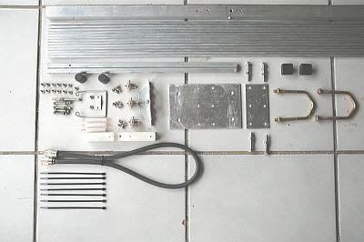
12 x 22mm x 5mm Stainless Steel Self tapping Screws
5 x 42mm x 4 mm Stainless Steel Machine Type Bolts
8 x 4mm Machine Type Nuts
3 x 52mm x 4 mm Stainless Steel Machine Type Bolts
12 x 4mm Stainless Steel Washers (plain)
12 x 4mm Stainless Steel Spring Washers
3 x SO239 Sockets
1 x 100mm x 25mm Angle Aluminum for SO239's
2 x 12mm Plastic End Caps to fit over driven element
26 X 6.5mm Plastic Caps to fit over elements
2 x 54mm x 6mm Stainless Steel Bolts
2 x 6mm Stainless Steel Washers (plain)
2 x 6mm Stainless Steel Spring Washers
1 x 6 meter  25mm x 25mm Aluminum Square Tubing (Boom)
2 x 6 meter 6.5mm Aluminum rod for Elements
1000mm x 12mm Aluminum tube for Driven Elements
2  x 25mm x 25mm Plastic End Cap to fit over or into the Boom
2 x U- Bolt TV Clamps
3 x PL259 Connectors
1 x 770mm RG213 Co-Ax Cable for balun
1 x  150mm x 25mm x 15mm Teflon Insulator
12 x 3mm x 10 mm Stainless Steel Machine Type Bolts (For SO239 fastening)
1 x 3.2mm x 500mm Aluminum Braizing Rod (For Hairpin Match)
1 x 130mm x 100mm x 5mm Aluminum Plate (Mounting Bracket)
1 x 100mm x 25mm x 3mm Aluminum Plate (Mounting Bracket Washer)
10 x Cable Ties (Tie RG213 Balun to Boom)
1 x 50mm x 10mm x 2mm Alumiinum Plate (Attaching plate (clip) for Hairpin Match)

I start off with measuring the boom length, marking the element placements and center punching the spot were the holes will be drilled for the elements.  One word of advice, never drill through both sides of the boom at once.  First drill one side then the other side.  This will ensure a centre hole on both sides.  After measuring and punching I drill the holes, first with a pilot drill (4mm) and then with the correct size (6.5mm) to fit the elements.   Holes drilled,  it is now time to drill the 4mm holes that will affix the elements to the boom.  I then take a 5mm thick self tapping screw and turn it into the 4mm holes drilled.  It will be hard to turn at first but this is necessary to ensure a good fit between boom and screw. Once you've made the SO239 holder, affix it and the insolator to the boom by drilling  the 4mm holes through the boom and SO239 holders.  Refer to the photo where exactly they must be fitted.  Also look at the photo's how to construct this holder, hairpin match, driven element insulator.  Put the boom aside as we will now first construct the balun.  Again refer to the schematic diagram of the photos in this regard.  Cut a 770mm piece of RG213 cable and install the PL259 connectors one on each side.  Do not cut of any piece of he RG213 as the cable must be 770mm from the one point (tip) of the PL259 to the other. Install the balun to the two outside SO239 connectors.  The middle SO239 will be used for the feedline.  Install the driven element and hairpin match.  Do not forget to fasten the hairpin shorting clip to the boom (Refer to photo for clarity.) You can now install all the elements and affix them to the boom.   Don't forget to align the elements.


Affix the boom-to-mast clamp and install the U-Bolts.  Nearly ready, but we haven't finish the installation of the balun to antenna connections.  Refer to the photo
for this process.  Ensure good soldering joints to the SO-239 connectors and use terminal lugs to affix to the driven element.  (See photo)  Waterproof the coax connections with Coax-Seal or some similar substance.  Install the plastic caps on the ends of hte boom, driven element and elements.  Use the 2 cable ties to secure the balun to the boom and more cable ties to tie the feedline to the boom and to the mast.   Be sure to insultate any connections from the boom or the mast. This completes the assembly procedures.

TUNING:
Driven Element:  The SWR can be lowered ot less than 1.2:1 at a desired frequency by carefully trimming the driven element.  Keep the element symmetrical by cutting the same amount from each side.  Typical SWR under normal conditions is 1.2:1.  Each installation however is different, so cut the driven element for the lower SWR at your particular location.   Measure the SWR as close to the antenna as you can for accurate results.  The SWR should be measured with the mast at right angles to the elements.  With the dimensions and material I used an 1.2:1 SWR was obtained.

PHOTO GALLERY:

Picture:  Driven Element , Hairpin, SO0239 Mount and Insulator

Picture:  Driven Element and Insulator

Picture:  SO-239 Mount (Outside view)

Picture:  SO-239 Mount (Inside view)

FINALLY:
As already mentioned this antenna is a real contest winner and especially suited for DX.  Why wait, get the aluminum and build this antenna and you will be surprised by it's "performance".  Hope to hear you on 144.400 Mhz soon!!


TEST RESULTS:    UPDATED: 26 March 2008!
The 10 Element 2 Meter Beam (front page photo) was installed and tested today (26 March 2008).  Unfortunately I do not have a MFJ Antenna Analyzer, but trust that somebody will sponsor me with one soon. (Wishfull thinking??)  So the only equipment I have to really test this antenna is the old faithful SWR meter and Field Strength meter.  This equipment have tuned many antennas in the past and this time was no different.  The following chart show the Bandwidth/SWR/Frequency of the antenna I constructed. The only difference is that I used 10mm tubing for the reflector and the driven element.  I obtained the following measurements:

SWR CHART:  FREQUENCY 144.400 Mhz - 147.400 Mhz; 50 WATT RF;  ANTENNA HORIZONTALLY POLARIZED;  6 METERS OFF THE GROUND


Frequency:SWR:Frequency:SWR:
144.400 Mhz1.3 : 1146.300 Mhz1.1 : 1
145.000 Mhz1.3 : 1146.400 Mhz1.1 : 1
145.200 Mhz1.2 : 1146.500 Mhz1.1 : 1
145.300 Mhz1.2 : 1146.600 Mhz1.1 : 1
145.400 Mhz1.2 : 1146.700 Mhz1.1 : 1
145.500 Mhz1.2 : 1146.800 Mhz1.2 : 1
145.600 Mhz1.2 : 1146.900 Mhz1.2 : 1
145.700 Mhz1.2 : 1147.000 Mhz1.2 : 1
145.800 Mhz1.1 : 1 147.100 Mhz1.2 : 1
145.900 Mhz1.1 : 1147.200 Mhz1.2 : 1
146.000 Mhz1.1 : 1147.300 Mhz1.3 : 1
146.100 Mhz1.1 : 1147.400 Mhz1.3 : 1  
146.200 Mhz1.1 : 1Bandwidth:3 Mhz

The Field Strength Meter confirmed an excellent front-to-back ratio with very little RF at the back of the antenna, but a full scale reflection on the meter in front of the antenna.  Very little reflection of the meter was noticed on the sides of the antenna.  I did not trim the driven element and the current length is as indicated in the construction section.

The following radio amateurs have used this antenna in contests:

Nico ZS4N
Terrence ZS2VDL
Allen ZS2BO
Johan ZS1I
Johan ZS2I

Acknowledgement:

Nico ZS4N - Antenna Measurements
Johan ZS2I - Photos of Antenna Components
Pieter ZR6AHT - Questions and Comments

More Photos:

Picture:  Boom Washer

Picture:  Hairpin and Clip

Picture:  Teflon Insolator  

Picture:  Driven Element, Hairpin and Insolator  

Picture:  Complete matching unit  

Picture:  Insolator (side view)

Picture:  ZS1I 10 Element Yagi installed 


Above :  ZS2I 14 Element 2M Yagi 

(Click on images for larger view.)


Wednesday, June 5, 2019

Broadcast Amateur Radio Bulletins and News Recordings with a Budget Studio Microphone, USB Audio Interface, VoiceMeeter Banana and Audacity.

 
Top Image:  ZS1I Broadcast Setup or VOIP Microphone Setup

Top Image:  Behringer Audio Interface

I have listened to various amateur radio bulletins and news flashes here in South Africa lately.  Noticeable was that in most of the cases the audio quality was rather poor to bad.  First things first if you want to compile a bulletin insert or news flash you must make sure that your audio quality is up to standard and of very good quality. There is nothing more irritating than to listen to bad audio. I know that there are many other ways to record audio files but I use what I have on hand. You will need the following budget equipment to compile a professional audio sounding file for your bulletin or news flash:

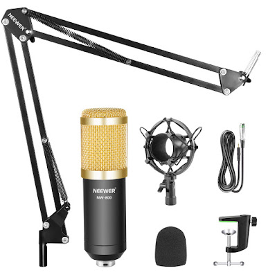
  1. At the very least a good quality professional condenser microphone with a shock mount.  48v Phantom Power required.
  2. A good quality Microphone Pop Filter.
  3. Microphone boom stand.  Any sturdy one will do.
  4. XLR Microphone cable.
  5. USB Audio Interface with microphone pre-amplifier and drivers.
  6. Laptop
  7. The following software:  a) VoiceMeeter Banana  b) Audacity.  Both are freeware.
I use the following settings in VoiceMeeter Banana and Audacity to record a good audio file.

VOICEMEETER BANANA SETUP:

Hardware Input 1

Select KS: Behringer USB Audio

A1
B2

Slider -0.4

Mute:  HI2 + HI3 + Virtual Inputs

Intelli Pan:  Set to middle left on line

Hardware Out: A1

Select MME: VB-Audio Point

Master Section

A1 + B2 Open

A2, A3, B1 Muted

A1 Slider =  -5.2
B2 Slider =  -4.5

AUDACITY SETUP:

Select:

Microphone:  MME  VB-Audio Point 1 (mono) Record

Speaker:  Select your laptop sound card output driver

The settings  of VoiceMeeter Banana can be saved for future use.

No Audacity effects need to be used.


Here are a few photos of the equipment  I use:


I find that the above setup gives me good audio, maybe not the best but what can you expect if you use  budget equipment.  What I can say is that the audio coming from this equipment is far more superior than the audio being broadcast by some audio bulletin compilers in South Africa.  I will not broadcast a bulletin with bad audio.  If you do it, it reflects badly on your ability to compile a good audio bulletin for your listeners to listen to.  Bad audio chase listeners away!

Give this setup a try and you will be amazed what can be achieved with fairly inexpensive equipment.